The RFID module uses various hardware components to collect movement information about users who carry a RFID tag. Each time a tag passes a receiver, it can be detected and the user's identification and location information can be gathered.
The RFID subsystem consists of the following hardware components, the network activator, Lantronix unit, network receiver, antenna, and RFID tags.
Activator Lantronix Unit Network Receiver
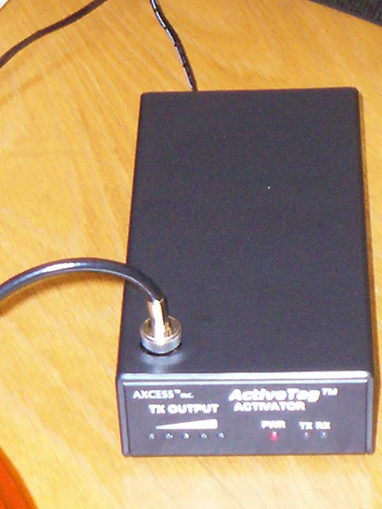
The Activator is a standalone transmitter which emits low frequency waves which activate tags which pass through the field of its antenna. It writes its location ID information onto the tag. This tag transmits this information along with its own tag ID to the receiver, when it passes through its field. Configuration of the Activator was done by connecting a serial cable between the receiver and a computer and by using the HyperTerminal application to setup the Activator ID.
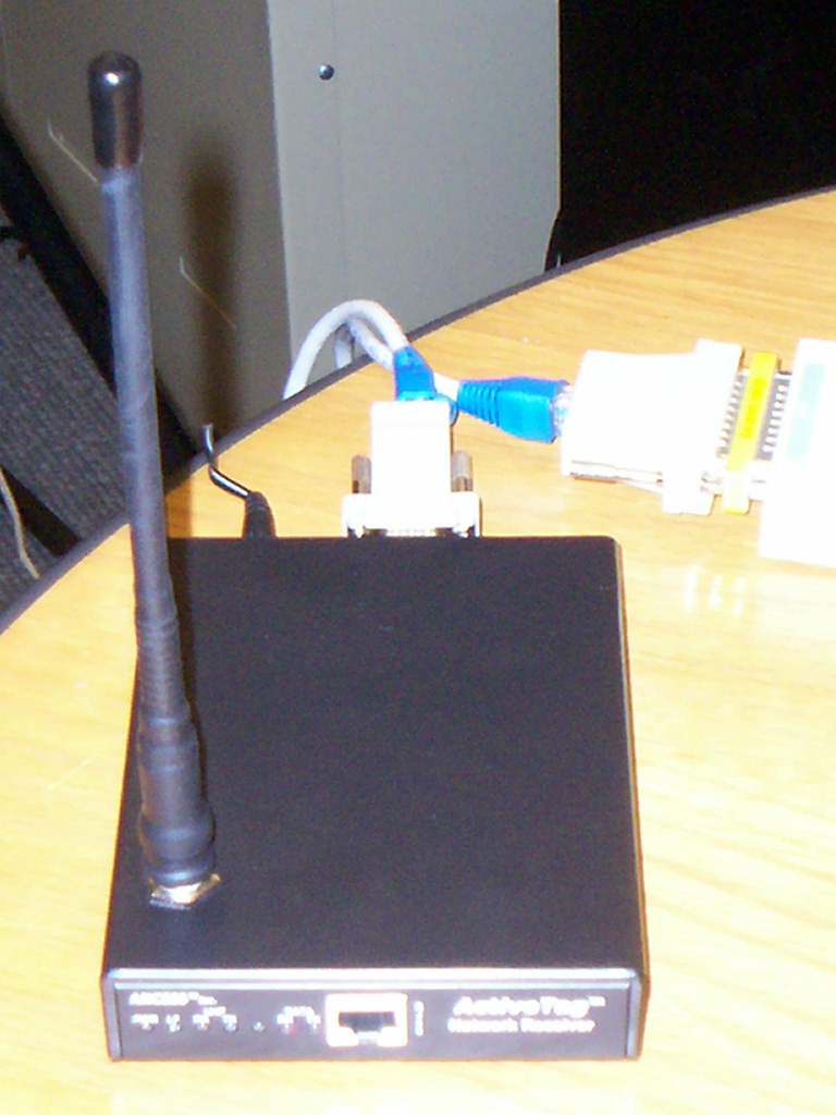
The Network Receiver has a small Unix like operating system incorporated into it, which can be used to configure it. The receiver has multiple functions such as decoding the signal received from a tag, converting it to a format usable by the computer system, filtering tag information according to the settings, sending data to the computer. Configuration of the network receiver is done by connecting a serial cable between the receiver and a computer and by using the HyperTerminal application to interact with the receiver's operating system. The parameter Receiver ID was setup during this configuration phase.
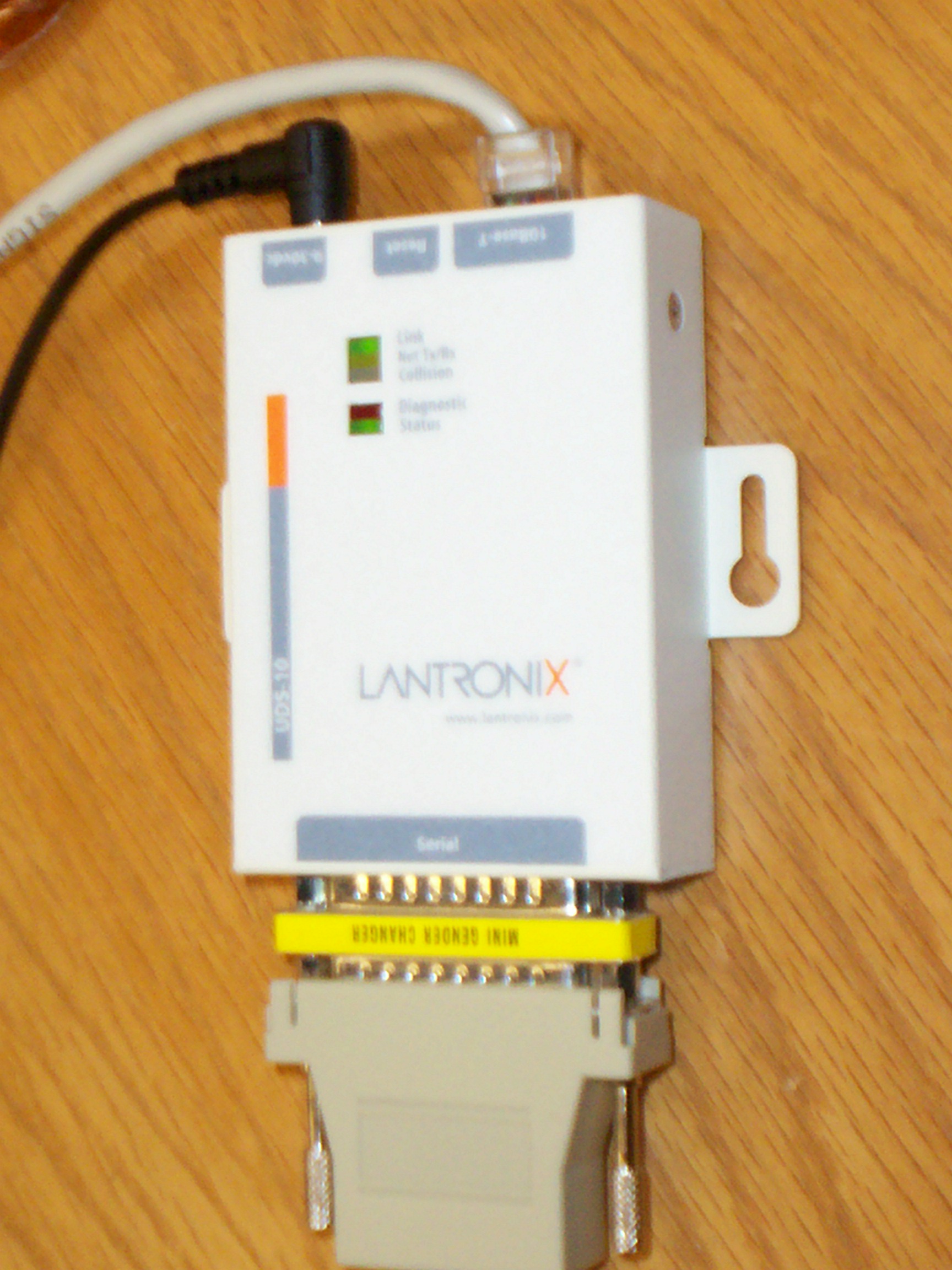
The Lantronix unit, in this case the UDS10 allows the Network Receiver to communicate and connect to Ethernet networks using the IP Protocol family. UDS-10 provides half duplex 10base-T Ethernet. It receives information from the receiver containing the tagID and Activator ID of the tag which passed through the its field.
The software program monitors port 3001 of the lantronix unit, to get the user tag and receiver id information. The information is then converted from its numerical form to a physical location address and to user identification information. This information is then sent to the presence server.
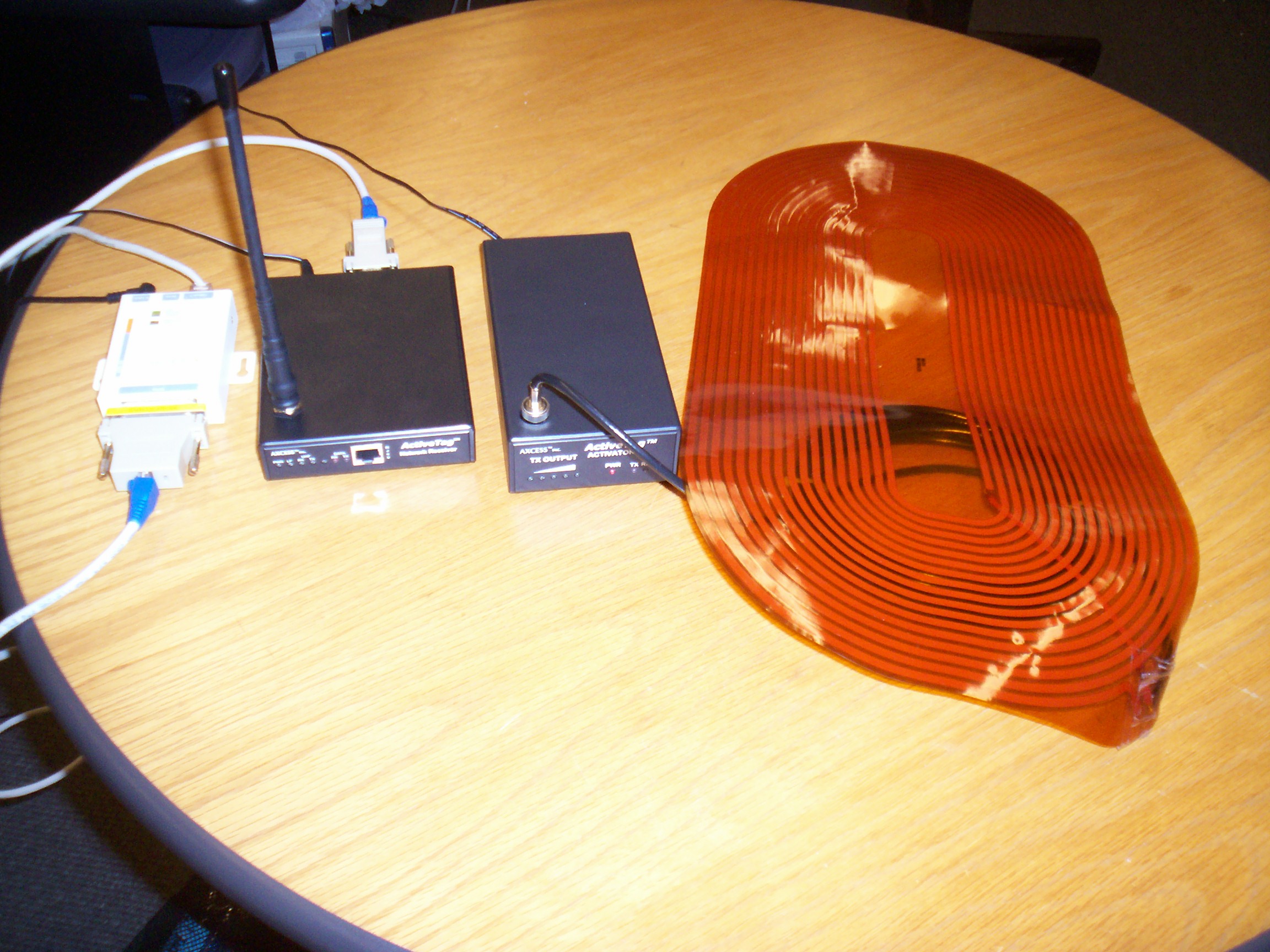
The flex antenna (the orange disk like antenna) is connected to the Activator unit.
The activator is powered up.
The Activator is configured by connecting it to a Computer using a Serial cable, and the HyperTerminal is used to change the Activator ID. This is done by typing a number followed by !. (example: 113!). Only certain numbers can be used for the ID.
The Network Receiver is setup the same way as the Activator. The Receiver ID is changed by typing a number followed by l, where the number can be between 000 and 999.
The lantronix unit is powered on and configured by connecting it to the computer using crossover cable. The static IP of the lantronix unit is set.
An Ethernet cable is used to connect the receiver to the lantronix unit. Another cable is used to connect lantronix unit to the LAN.
The hardware setup is complete.
Operating System : Windows.
Language: Java
Software: MJSIP sipstack and Publish Class
Hardware: Lantronix unit, Network Receiver and Activator, RFID tags associated with users.
Lantronix unit needs a static IP address.
Setup: Predefined mapping between network receiver and location.
Predefined mapping between RFID tag and user.
Configuration: The network receiver and activator need to be setup, so that each receiver and activator has its own unique identifier, as described under Hardware Setup.
Configuration File: A configuration file is used by the module to setup the presence server information it needs.
The project Final ABD contains the following directories
1) log: log files are kept which show the publish messages and the responses received to them.
2)config: configuration files such as rfid.cfg which lets users setup username, hostname and dest-port information.
3) lib: contains all the jar files needed the project such as sip.jar (sip stack).
To run the program: java -classpath lib\sip.jar;rfid.jar BusyDiscovery.rfid.RFIDmodule
The configuration file is read using the Parser Class which is part of the MJSIP library. The format of the configuration file is as follows:
# Automated Busy Discovery RFID configuration
file
# ___________________________________________
#
# ********** sip ***********
local_port=5060
username=Rekha
hostname=cs.columbia.edu
rfid_mapping=RFIDmapping.txt
recv_mapping=ReceiverID.txt
The local_port parameter contains the information about the port that the sip stack is listening on for incoming responses. The username host name parameters are used in the creation of the PUBLISH message such as for the SIP Request. The rfid_mapping and recv_mapping parameters contain the file names where the mappings between users and tag and receivers and locations is stored.
The mapping files used are RFIDmapping.txt for mapping tags to users, and the ReceiverID.txt which is used to map locations with receivers. These files are read into java Properties, so that the program can get a user's/location's information without having to iterate through the file repeatedly.
A sample of the RFIDmapping text is shown below:
01871 John,Matthews
01872 Peter,Johnson
00051 Daisy,Fernandez
where the five digit number represents a tag ID, and the user's name who is associated with the tag.
A sample ReceiverID text is shown below:
001 CS Lounge, Mudd, Columbia University
002 7LW2,CEPSR,Columbia University
where the three digit number represents a
receiver ID; the string gives the location of the receiver.
The program gathers its information by monitoring port 3001 of the lantronix unit. The information gathered originates at the network receiver. The network receiver gets the tag information of all tags which pass through its field. After doing the required processing on this information, it creates a string which is passed onto the lantronix unit. This string is of the form
R R R A A A F F F T T T T T LF CR
where R R R stands for the Receiver ID
A A A stands for the Activator ID
F F F stands for the facility code
T T T T T stands for the tag ID
LF stands for line feed
CR stands for carriage return
The program can then access this information by reading port 3001 of the lantronix unit. It does so by setting up a TCP socket connection between itself and port 3001. It uses the regular TCP protocol to set up the connection. The received string can then be parsed into its subparts contained Activator ID ,Receiver ID , tag ID information.
The Receiver ID information is then matched with information from the Receiver mapping file to get the physical location of the receiver; the tag ID information is matched with information from the RFID mapping file to get the user's specific information such as their name.
The location and user identifier information is then sent to the Publish class, where the publish message is created and sent to the presence server. The location and user information is translated to PIDF and forms the body of the PUBLISH message. The PIDF skeleton structure is fixed with each module filling in information such as the location, activity of the user, username and whether they are busy or not, which is set in the <basic> xml element as closed or opened.
Sample Publish Message:
PUBLISH sip:Rekha@cs.columbia.edu SIP/2.0
Via: SIP/2.0/UDP honamsun.cs.columbia.edu:5060;rport;branch=z9hG4bK42589
Max-Forwards: 70
To: <sip:Rekha@cs.columbia.edu>
From: <sip:Rekha@cs.columbia.edu>;tag=z9hG4bK97843157
Call-ID: 652825108423@honamsun.cs.columbia.edu
CSeq: 1 PUBLISH
Contact: <sip:Rekha@cs.columbia.edu:6060>
Expires: 3600
User-Agent: mjsip stack 1.6
Event: presence
Content-Length: 797
Content-Type: application/cpim-pidf+xml
<?xml version="1.0" encoding="UTF-8"?>
<presence xmlns="urn:ietf:params:xml:ns:cpim-pidf"
xmlns:local="urn:automatedBusy:pidf-status-type"
xmlns:dm="urn:ietf:params:xml:ns:pidf:person"
xmlns:es="urn:ietf:params:xml:ns:pidf:status:rpid-status"
xmlns:et="urn:ietf:params:xml:ns:pidf:rpid-tuple"
xmlns:ts="urn:ietf:params:xml:ns:pidf:timed-status"
entity="pres:Rekha@cs.columbia.edu">
<tuple id="ee2924f3">
<status>
<basic>closed</basic>
<dm:person>
<et:class>Daisy,Fernandez</et:class>
<dm:status>
<es:activities>
<es:activity>DYNAMIC</es:activity>
</es:activities>
</dm:status>
</dm:person>
<local:location>CS Lounge, Mudd,Columbia University</local:location>
</status>
</tuple>
</presence>
The system was tested using the various RFID tags. The receiver and activator have a limited range, so tags were taken in and out of the devices range and the information variation was observed by the program.
A single tag is taken into the field of the receiver, and the publish message is observed. The tag is moved further and further away from the receiver and the programs activity is observed.
Multiple tags were taken into the field of the receiver at the same time and the program was observed.
Some of the RFID tags seemed to be more powerful. For example if multiple tags were present, some of the tags were detected with a greater frequency than others.
The range of the network receiver is supposed be 35 feet according to the specifications, but the range was found to be less than 20 feet, which may have been because of the structure of the room.
There will be an adequate placement of receivers to track users efficiently.
Setup of the various hardware components.